
SGS – Synchronous Generator Study in C++ Visual Studio
Research work of ELECTRICAL MACHINES II “EE-214”
Introduction
This is an undergraduate research work, which was assigned to me when I took the course of Electrical Machines II at the National University of Engineering (Lima-Peru), in 2001, which consisted in making a study at academic level of any three-phase synchronous generator, from its basic electrical parameters: nominal power (Sn), voltage (V), active power (P), reactances in unit values Xd and Xq.
This work was carried out together with my university friend Victor Ibañez Piscoya, with whom we dedicated ourselves to the research and development to solve this problem, with the advice of our professor engineer Luis Rojas Miranda, and in this way we developed the corresponding theoretical formulations to obtain the results of the Generator Study.
There was an alternative to develop the calculation work in Matlab or Excel, solutions that were adopted by most of my classmates, but thanks to my experience gained developing software in C++ for windows, with programs like Fractal X, BM5GL, etc, with my partner university friend we decided that I would be in charge of developing a software elaborated in Visual C++, with a friendly and easy to use interface, to study any three-phase synchronous generator.
Problem to solve
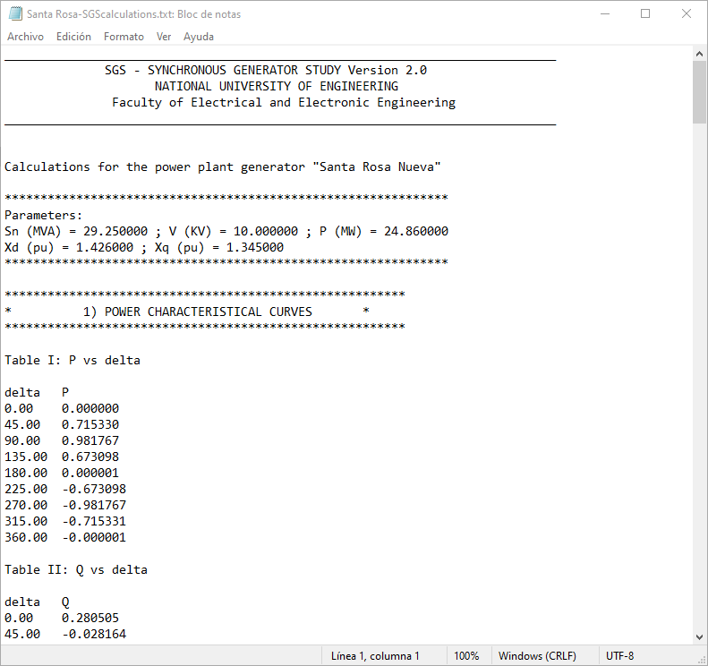
A 3φ synchronous generator operating in our electrical system has the following characteristics (Santa Rosa Nueva – Power Station):
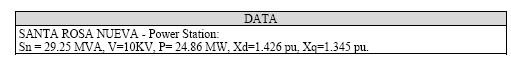
Assuming the armor resistance and losses are negligible, we ask:
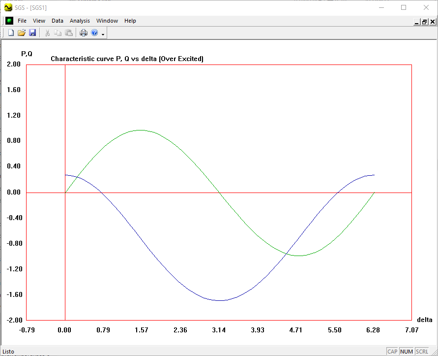
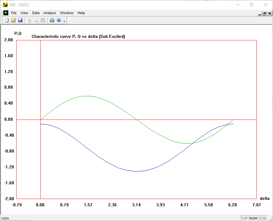
- Draw the characteristics P-δ, Q- δ considering:
- V = 1.0 pu y Ef = 1.4 pu
- V = 1.0 pu y Ef = 0.85 pu
- The generator must supply a symmetrical load that has a variable power factor and that requires a KV voltage in all regimes. To do this, it will be necessary to interact with the water, gas or fuel intake valve of the turbine and with the excitation current of the generator.
- If the current required by the load were the nominal current (In) of the generator, calculate the excitation current in p.u. and the delta angle for: cos = 1; 0.8, 0.6, 0.0 inductive and 0.8, 0.6, 0.0 capacitive
- For the power factors given in (2.1) and if the load current were I = K(In). Calculate the excitation (Ef) and the angle δ for values of K =1.25, 0.75, 0.5, 0.25.
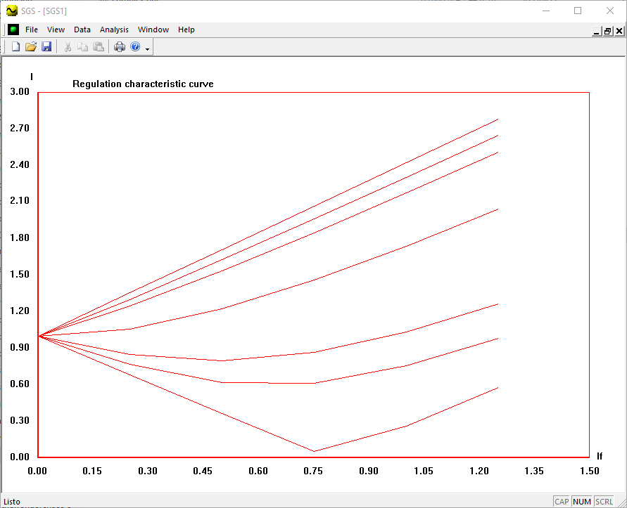
- Construct the regulation characteristic If = f(I) for all the cases studied in 2.2
- The generator is connected in parallel with a EPS (electrical power system) whose voltage is Vsist = 1.0 p.u. If the generator must deliver its nominal current (In).
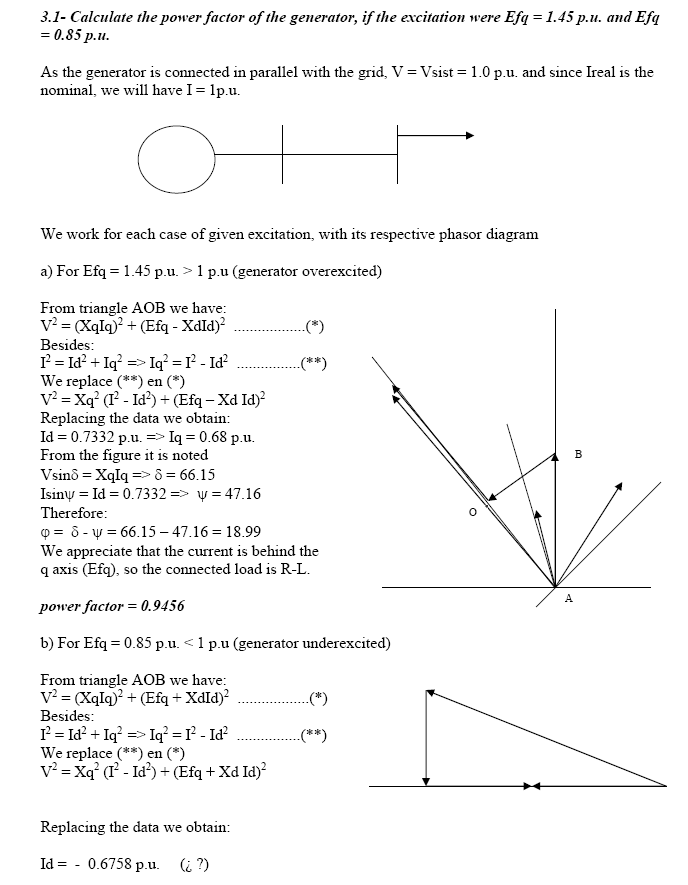
- Calculate the power factor of the generator, if the excitation were Efq = 1.45 p.u. and Efq = 0.85 p.u.
- What is the power factor of the generator, for which the voltage at the terminals is equal to the e.m.f.
- The water, gas or fuel intake valve of the turbine is adjusted so that the generator delivers to the system (Vsist = 1.0 p.u.) a power of P = 1.0 p.u. Then, without changing the position of the intake valve, the excitation current is varied so that in no case is the generator current greater than 1.25 p.u. Calculate:
- The excitation, generator power factor, reactive power and generator current.
- What would be the minimum excitation with which the system would still continue operating.
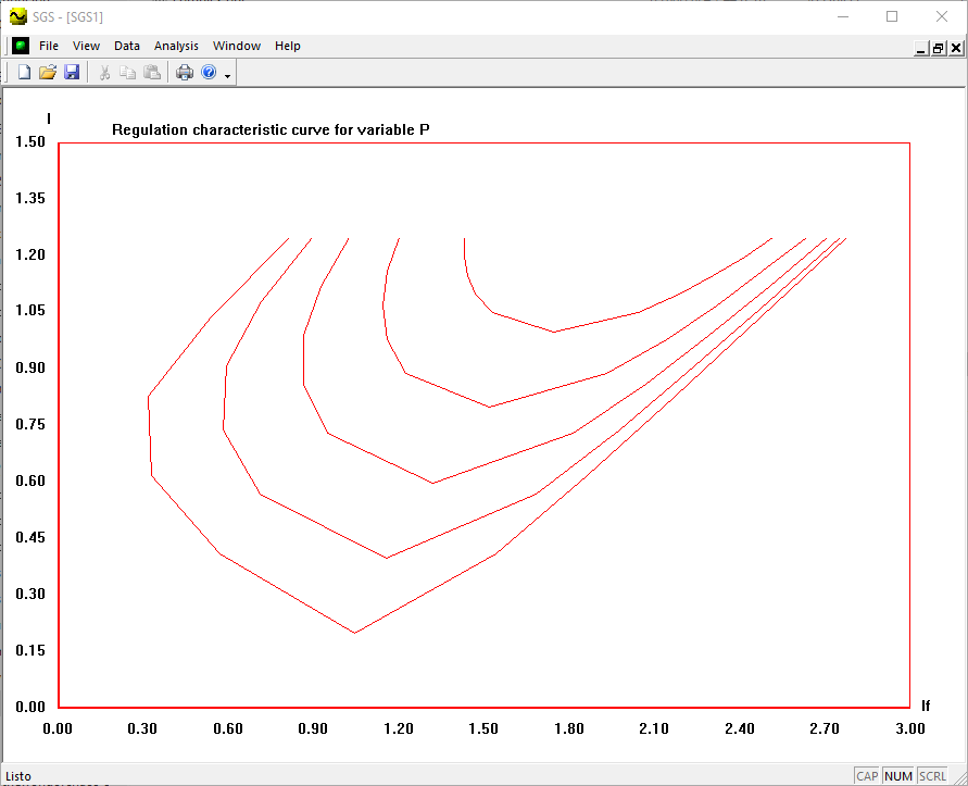
- Perform 4.1 y 4.2 if P = 0.8 ; 0.6 ; 0.4 ; 0.2 p.u.
- Graph the I vs if characteristics for each P
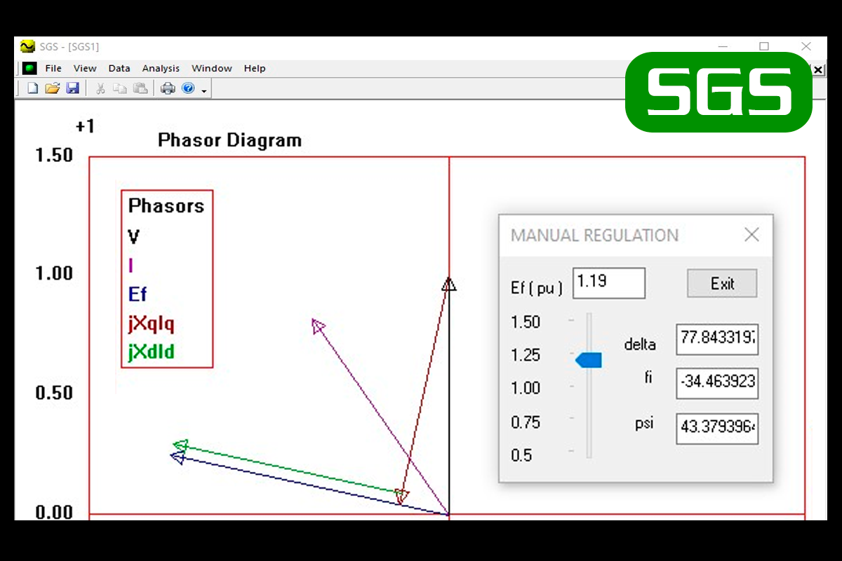
Technical aspects
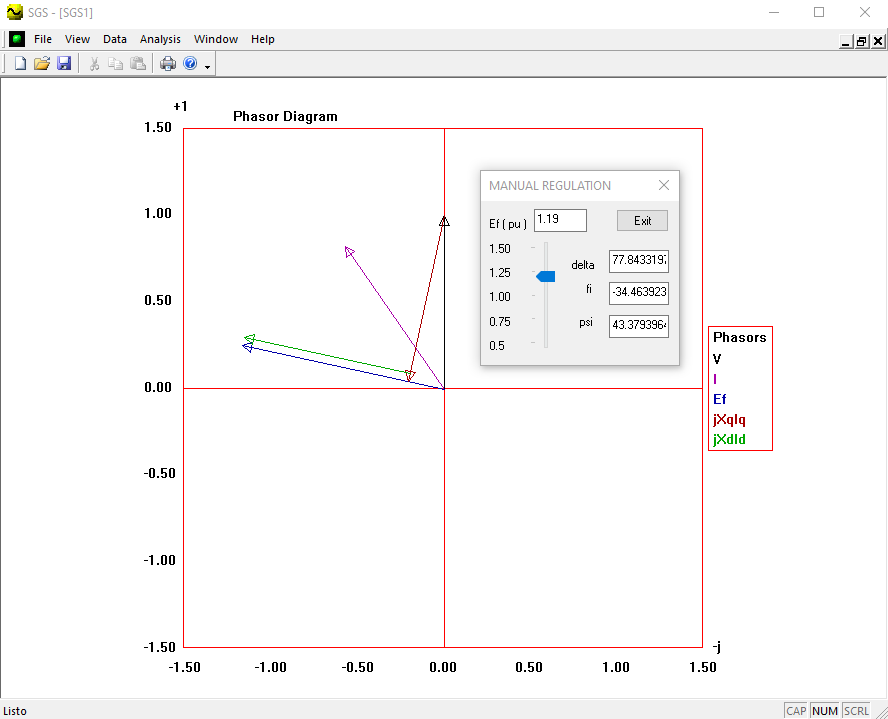
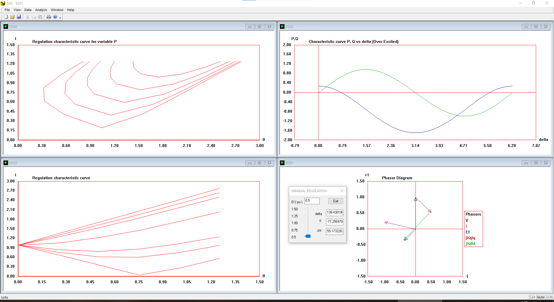
Software written in Visual C++ that allows to vary the excitation voltage of a generator through a Windows slider control and to see how the vectors and graphs vary, when sliding the control.
You can download the software executable for FREE from here:
Get the SOURCE CODE of “SGS software” and increase your programming experience:
Source code available in Visual C++ 2017 project.
By exploring the source code you will learn:
- Get access to the research work document in PDF format (45 pages). Includes original version in Spanish language and version in English language.

- How to solve and plot the exitation curves of the synchronous generator.
- Explore the source code of the slider interface to control the excitation voltage and see how the vectors and graphs vary as you slide the slider.
- How to plot curve graphs in an XY region in Visual C++ using the MFC and the CDC class.
- How to make reports in txt text files of the generator excitation
Credits:
Programmer:
JOSE LUIS DE LA CRUZ LAZARO
Fundamentals and theory about the Synchronous machine:
- JOSE LUIS DE LA CRUZ LAZARO
- VICTOR IBAÑEZ PISCOYA
YACSHA – Software & Desing, since 1999, Lima – Perú
The World of Chaos – EL MUNDO DEL CAOS – Unlimited Programming
HISTORY
Version 2 – 12-VI-2024
- Porting to VC++ 2017
- Improved: The main menus are simplified, eliminating unavailable options
- Improved: Option added to the Help menu to visit the World of Chaos website
- Improved: The Interface is translated from Spanish to English
- Improved: The reports are translated from Spanish to English
- Fix: Some texts that were hidden after translation or modification are completely shown
- Improved: Working directory is changed
- Improved: gitignore is updated so that it does not delete txt files in Release
- Improved: Added example reports for two power plants od Peru: Santa Rosa Nueva and Santiago de Cao
- Fix: Corrected excessive tabulation in the SGScalculations.txt report
- Improved: The class complex(complex.h) has been obsolete since it is currently preferable to use the standard std::complex class. But for backward compatibility, a complex_plus name_space has been created where the phasor function and some necessary constants such as PI, _i and _j have been defined.
- Fix: The float type is changed to a double type
- Improvement: The Research Work document is added and the folders are reorganized
Version 1 – 09-II-2001
- Original version for VC++ 6.0